 Petlowany Three-Band Burner Antenna Petlowany Three-Band Burner Antenna
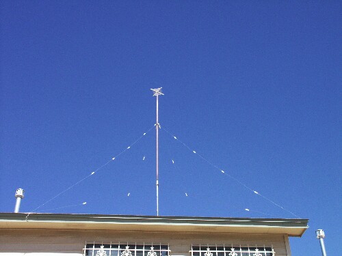
June 23, 2002The Petlowany Three-Band Burner is a simple, low-cost, trapless short vertical antenna which amazingly works on three HF bands (20, 15 and 10 meters). This web page contains pictures, performance data, and enough construction details so you can "homebrew" your own.
 Petlo... Who?
Basic DescriptionPerformance-wise, it is pretty much indistinguishable from a quarter wave ground plane vertical on all three bands. As such, it does a reasonable job of delivering the low angle radiation required for DX operation.
Here are the three bands that give the Petlowany Three Band Burner its name.
 Construction
Details
Construction
Details
Making
the spiral topThe spiral coil is wound on a form built of half inch PVC pipe. The first step is to make the coil form. Cut four pieces of half inch PVC 20 cm long. Insert one of them into the half inch PVC cross as far as it will go. Make a mark on the pipe where you would be able to drill a 3/16 inch hole as close as possible to the cross without touching it. This is the hole through which the first turn of the spiral coil will pass.
Remove the pipe from the cross and make additional marks every 2 cm all the way out to the end (the long way, away from where the cross fits). Use the first pipe as a template and mark the other three pipes the same way. Now drill 3/16 inch holes as marked, all the way through both sides of all four pipes.
Using PVC cement, glue the four pipes into the cross to make the coil form. Be sure to glue the right ends of the pipes, so the innermost hole is close to the cross without being obscured by it. Take care also to keep the holes in line with the plane of the cross, so a coil can be wound, as in the picture.
Use 5 meters of 12 ga. wire for the spiral coil. Any type of wire is suitable electrically. I used wire with a slick insulation for ease of threading through the coil form. Starting from the inside, leave 10 cm of slack for the inner coil connection, and thread the wire through all four innermost holes in the coil form, pulling it tight.
Continue to thread the wire progressively outwards in a spiral shape, pulling it tight as you go. Make sure you always have the 10 cm of slack inside for the connection to the pipe. When done, use a cable tie to keep the wire from slipping back out, as shown. To reduce wind resistance, you may wish to saw off any excess length on the coil form arms. (The ones in the picture have not been trimmed.)
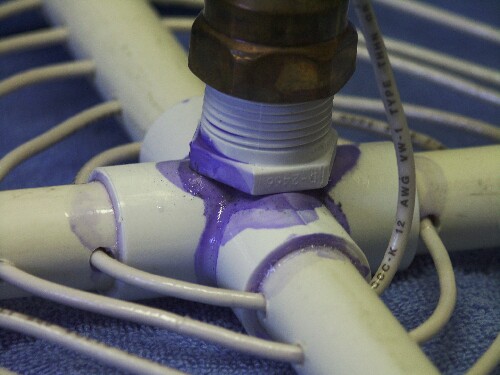
The final step in making the spiral coil is attaching the 3/4 inch male PVC plug to the side of the cross, so the coil can be screwed down onto the copper pipe. To do this, rough up one side of the cross with sandpaper. If you will do most of your communication in the Northern Hemisphere, let the coil run clockwise... (just kidding!). Also rough up the flat end of the 3/4 inch PVC male plug. Slather on some PVC cement and hold the plug in place until the glue has a chance to set up. Here is a close-up picture of the joint between the plug and the cross. It may not look strong but PVC cement forms a strong chemical bond. Do not screw the plug into anything until the glue dries overnight.
Now that you have the coil, you must make the pipe portion of the antenna top. This is easy. Sweat a 3/4 inch female adapter onto each end of a 20cm length of 3/4 inch copper pipe. (If you wish to experiment with tuning, you might want to leave one end unsweated (as shown) and/or start with a longer length of pipe. If you wish only to duplicate my results, don't worry about getting the length perfect -- the tuning is very forgiving, in terms of the length of the vertical element.)
As you can see in this detailed photo, I sweated on mounting brackets near the top end to make available four holes at right angles. Once I'm sure I won't want to take down the antenna for a while, I might use those to attach ropes to steady the top of the antenna. For now, though, I prefer not to use the ropes. It is so much easier to take the antenna down without them. Even if you don't plan to use ropes, you must sweat on something that will allow you to solder the spiral coil wire without damaging the PVC plug on the coil form with excessive heat.
To complete the spiral top assembly, screw the coil form into the pipe, with the mounting brackets (or other soldering post) toward the top. Cut off any excess length and solder the inner end of the spiral coil to the bracket or post. Be careful not to damage the PVC plug with heat.
When completed, your spiral top should look a lot like the one in the photo.
 Making the main
vertical element
Making the main
vertical elementThe vertical element is chiefly a 10 foot length of one inch copper pipe. The only critical thing about this assembly is that it is necessary to slide a guy ring over one end of the pipe before sweating the top end on.
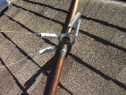
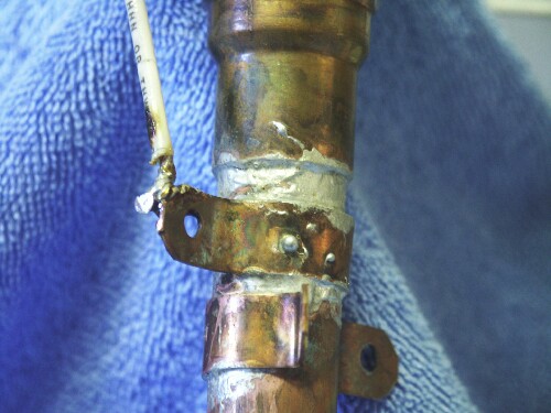
Choose an end of the pipe to be the bottom and sweat on a one inch male adapter. Also sweat a piece of wire (I used 14 ga. solid but it is not critital) to the bottom end for attachment to the feed line. In this detailed photo, the wire can be seen as a ring just above the male adapter sweat joint, and also where it attaches to the coax.
About six feet from the bottom end, sweat on a ring consisting of a few turns of solid wire. This ring will stop the guy ring from sliding down. (The picture at the beginning of this section shows this ring stopper in detail.)
Slide a guy ring onto the top of the pipe, making sure it is the right way up (skirts point down). Be sure the ring you just soldered onto the pipe holds the guy ring in place. Also make sure the guy ring can turn freely while straining against the stop. This will make it much easier to install and take down the antenna.
Finally, sweat a 3/4 inch male adapter (for 1 inch pipe) to the top end of the pipe. This will attach to the spiral top when the antenna is assembled.
 Preparing the
base
Preparing the
baseThe base of the antenna consists of a galvanized pipe which acts as a mast and a PVC "barrel" which secures the antenna to the mast mechanically without connecting it electrically.
To make the PVC barrel, simply cement two one inch PVC female adapters to a short length of one inch PVC. The pipe should be just long enough that the two adapters touch or nearly touch.
Before screwing the barrel onto the mast, it will be necessary to slide a guy ring on. If you use the recommended radio shack guy ring and one inch galvanized pipe, the guy ring won't quite fit over the end. Use a grinding or reaming tool (I used a dremel) to increase the size of the hole in the guy ring. It is not necessary to make it fit over the entire pipe. It only needs to be able to slide down over the threads enough that the barrel can screw on securely.
Slide the guy ring over the top of the mast, using the included bracket if necessary to keep it from sliding down. Screw the PVC barrel onto the top.
 Making the
radials and guys
Making the
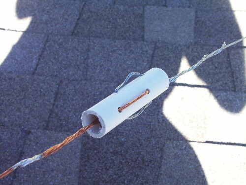
radials and guysBoth the radials and guys require insulators. If you have 24 good quality egg insulators, by all means use them. I had trouble finding any and decided to use PVC to make low-cost insulators. As you can see from the picture, I drilled four 3/16 inch holes through a 4-inch piece of half inch PVC, with interlaced pairs of holes at right angles. (No way that language would be clear without a picture!) The advantage to this approach is that the wires are actually linked, so when the PVC inevitably rots from the sun's UV rays, the structure is still mechanically secure. That's the theory, anyway. Note the way each wire is threaded into one end, out and over the side, then through to the other side, over and back in, then out the end again.
Once you have made or otherwise obtained 24 insulators, you are ready to prepare the radials and guys. We'll start with the radials.
To make the radials, cut four lengths of 12 ga. copper wire slightly longer than 3.5 meters, such that the radial will be 3.5 meters long once the ends are wrapped around the guy ring at the base and the insulator at the other end. Attach an insulator to one end of each radial. Solder the wire as shown for extra strength.
Attach the non-insulator end of each radial to the guy ring at the top of the mast (just below the PVC barrel). Do this by making a loop and soldering it as shown in this detailed photo. Solder a loose ring of copper wire to each loop, all the way around the guy ring, to ensure that the radials are electrically connected at all times. Coil up and tie the radials neatly. They are now part of the base, ready to install on the roof.
To make each guy, use steel guy wire to construct a string of five insulators spaced one meter apart, for a total length of 4 meters per guy string. (Longer, electrically continuous guy segments can mess up the antenna's performance.) Make 4 guys, using a total of 20 insulators.
Use the shortest length of steel guy wire possible to attach the insulator on one end of each guy string to the guy ring that slides freely on the main vertical element. This detailed photo shows how. Neatly coil up and tie the guy strings. These are now part of the vertical element, ready to install.
 Installing the base
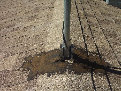
Find a suitable location at the apex of your roof, surveying where the radials and guy wires will go. Avoid power lines for safety. Once you find a good spot, screw the roof mount down securely with lag screws. Use roof tar to weatherproof the mount as shown before the next rain or snow.
Install hooks for the guy wires and radials at four locations such that the radials will be spaced as evenly as possible (90 degrees apart), and such that the radials can be fully extended (3.5 meters from top of base) and not yet reach the hooks.
Place the mast near the mounting point. If an assistant is available, the mast can be held in mounting position. Run the radials out toward the hooks (they shouldn't reach yet) and secure them to the hooks with a length of steel guy wire extending from the insulator to the hook. This picture shows what the insulator looks like with one copper wire and one steel wire. Leave enough slack that the radials can be under tension, fully extended, once the mast is raised. Without an assistant, getting these lengths close enough to let go is cumbersome. Be patient and don't risk letting the mast get out of your control.
Once the mast is basically in place, adjust the tension at the hooks until the radials are fairly taut and the mast is vertical and feels secure. Tighten the mounting screws and lock nuts in the apex mount to complete the installation of the base.
 Adjusting the guys
Attach fairly long pieces of steel guy wire to the end of each guy string, and secure them to the hooks. It should be possible to raise the vertical element near to its mounting position without straining the guys. Now slowly and patiently, progressively shorten the guys at the hooks until they are just long enough to permit the vertical element to be raised into position and screwed into the base. (Having an assistant is extremely helpful.)
Completing the installationThe only critical adjustment is the length of the coil, which mainly affects performance on the 20 meter band. 5 meters is a bit too long for the spiral coil wire, so you should find that the antenna is initially resonant somewhat below 14.2 MHz. Carefully lower the antenna repeatedly, shortening the spiral coil to bring the antenna into resonance near 14.2 MHz. I ended up with a 4.75m coil length. If you were able to duplicate my design parameters, you should find the performance on the 15m and 10m band to be as shown in the SWR charts.
 About N5IZU
I still feel I know so little. I've put this project on the web in the hopes that someone will write me a breathless email one day, explaining, "No, -DT, you've got it all wrong! A little change here and there and you can have five bands!" Even more exciting would be to learn exactly how and why it works the way it does.
In the meantime, it is nice to just enjoy it for a while. Recently I've been content to just haunt the bands, chasing whatever DX gets snared in the burner.
Go
 to
-DeeT's Hacks Page.
to
-DeeT's Hacks Page.
David B. Thomas (dt@dt.prohosting.com)