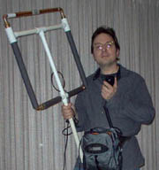
 Portable HF Transmitting Loop Antenna
November 12, 2004
While HF antennas are not normally known for their small size,
magnetic loops can offer quite respectable performance, at the cost of
some efficiency and extremely narrow bandwidth. This tunable magnetic
loop antenna is my contribution to the well established art of amateur
loop making. It is small and light enough to carry while operating,
it disassembles into small but rugged pieces
that fit easily in a backpack or gym bag, and it can be tuned from 14
MHz to 30 MHz.
Specs in Brief
Frequency coverage: 14-30 MHz
Efficiency: 32%@14, 54%@18, 66%@21, 78%@25, 87%@30 MHz
Bandwidth: 12k@14, 20k@18, 30k@21, 50k@25, 100k@30 MHz
SWR: 1.0:1 where tuned
Power Handling: tested at 20W PEP
Size: 21 inch square plus handle
Weight: 4.5 pounds
Theory of Operation
For those unfamiliar with magnetic loop antennas, the principle behind
them is simple. A small conducting loop (often on the order of 1/10
wavelength) is broken and a capacitor bridges the gap. The loop's
inductance, combined with the added capacitance, forms a high-Q tank
circuit. A coupling loop or other matching network delivers power
from a transmitter, exciting the tank circuit at its resonant
frequency. By changing the capacitance, the antenna can be tuned over
a fairly broad range of frequencies.
For any given tuning, bandwidth is very limited, due to the high Q of
the circuit. Efficiency is limited by the resistance of the
conductor. While the resistance of copper pipe is vanishingly small,
the radiation resistance of such a tiny radiator is often even
smaller. My loop, for example, has a radiation resistance of 20
milliohms at 14 MHz, but its ohmic resistance is more than 40
milliohms! The lost power (two thirds of it in this case) does little
for global communication, though it may contribute ever so slightly to
global warming. ;^)
While an efficiency of 32% at 14 MHz might not sound terribly
inviting, I am grateful to be able to carry around a small, light
antenna that performs one third as well as a 33 foot dipole up 16 feet
in the air. If it is possible to work the world with 5 watts into a
dipole, then 15 watts into this loop should do equally well.
 Construction
Except for the coupling loop, which is made from RG-58 coax, the
entire antenna is made from hardware store parts.
Parts List
- 1/2 inch copper pipe (approx. 5 feet)
- 3/4 inch copper pipe (approx. 1 foot)
- 1/2 inch copper repair coupling (12 inch long)
- 3/4 inch copper repair coupling (12 inch long)
- 3/4 inch schedule 40 PVC pipe (approx. 5 feet)
- 3/4 inch "PEX" polyethylene pipe (approx. 1 foot)
- 1/2 inch copper elbows (3)
- 3/4 inch to 1/2 inch copper reducing elbow (1)
- 1/2 inch copper unions (4)
- 3/4 inch PVC cross (1)
- 3/4 inch PVC tee (1)
- 1 inch to 3/4 inch PVC reducing tees (2)
- foam insulation for 1/2 inch copper pipe (approx. 5 feet)
- RG-58 coax (approx. 6 feet)
 Building the Main Loop
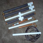
The main loop consists of the five pieces
shown here. First, the pieces are built without soldering or
cementing, to ensure that they fit correctly. Once a good fit is
verified, soldering can be done. It is not necessary to cement any of
the PVC parts.
 The PVC Cross Bar
The PVC cross bar is very easy to make. Two 8.375" lengths of
3/4" PVC are inserted into the 3/4" PVC tee. As a
double-check that the lengths are correct, and that your PVC parts are
the same as mine, temporarily attach the two PVC reducing tees to the
ends, as they appear in the picture of the
assembled main loop. The centers of the reducing tees (and thus
the centers of the copper pipes which will later pass through them)
should be exactly 21" apart.
 The PVC Vertical Support
This piece will later contain the coupling loop. For now, simply cut
a piece of 3/4" PVC pipe 14.75 inches long.
 The Bottom Conductor
This piece forms the bottom of the transmitting loop. Underneath the
pipe insulation and PVC cross is a single, straight piece of 1/2"
copper pipe terminated in the threaded ends of two unions.
Cut the copper pipe as needed to place the ends of the unions
17.75" apart. Do not solder anything yet. The foam insulation
and PVC cross can be added later.
 The Left and Right Side Conductors
In my design, these two pieces are very nearly the same size, but not
quite. The loop is not quite symmetical, due to the asymmetry of the
variable capacitor. It would be possible to modify the design
slightly, so that the two side conductors are the same size. All that
would be necessary is for one of the variable capacitor pieces (the
stator assembly) to be made slightly taller to compensate. I welcome
you to make this change if you wish, but I have chosen to only
document what I have actually done.
The two side conductors are made from a straight length of 1/2"
copper pipe with the threaded end of a union on one end, and a
1/2" elbow and the nut end of a union closely attached to the
other. It will be necessary to cut a short "filler" piece
of 1/2" copper pipe to attach the elbow to the union. Be sure to
leave enough of that piece exposed for soldering (about 1/8").
When assembled, the left side conductor's length is 19.125 inches,
measured parallel to the long pipe, from the center of the
nut union-end to the end of the threaded union-end.
The right side conductor, measured the same way, is 18.75 inches.
Hold off on soldering anything for the time being.
 Verifying a Good Fit
Slide the 3/4" PVC cross over the bottom conductor and the
reducing tees over the tops of the side conductors, screw the unions
together, carefully assemble the pieces, and see if they
form a nice looking letter "U" shape.
The side conductors should be parallel and 21 inches apart, measured
center to center. Attach the PVC vertical support and PVC cross bar,
verifying that these support pieces will fit comfortably over the pipe
when later centered over each piece by the insulation material.
The tops (threaded union-ends) of the side conductors should be 21
inches apart, measured center to center and parallel to the bottom
conductor. Since the side pieces are of slightly different lengths,
the left side of the "U" shape will be 3/8" longer
(taller) than the right side (unless you've chosen to make them the
same, as described earlier).
If everything checks out at this stage, in theory you could now start
soldering. However, it is a good idea to make sure that the variable
capacitor fits on the loop well, and the solder all the copper parts
at once. Also, in the soldering step I will make suggestions as to
how to get the PVC cross where it is needed (it won't slide over the
union-ends), how to apply the insulation, etc. So for now, let's set
these parts aside and start on the variable capacitor.
 Building the Variable Capacitor
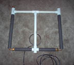
The variable capacitor is made up of the
four pieces in this picture.
 The Stator Assembly
The stator assembly is comprised of a 9 inch length of 1/2"
copper repair coupling, a 1/2" copper elbow, and the nut end of a
union. A short piece of 1/2" copper pipe must be used to attach
both ends of the elbow. Cut these "bullet" pieces long
enough to leave approx. 1/8" of copper exposed in each joint.
(Add an additional 3/8" on the union side if you chose to deviate
from my design and make the left and right side conductors the same
length.) Don't worry... it's almost time to begin soldering. Hang
in there!
 The Dielectric Sleeve
This is a 10 inch length of 3/4" PEX polyethylene
pipe. Resist the temptation to use CPVC, which actually fits more
easily here, because it is a lossy dielectric. When you transmit,
CPVC sucks up a substantial portion of the energy by getting hot. PEX
remains cool as a cucumber, letting your power go out over the air
where it belongs.
As it comes from the hardware store, the PEX pipe's inner diameter is
a little too small to fit over the copper repair coupling. If you
have a lathe, great! I didn't, so I used a 11/16" speed bit
(spade shaped) to bore out the pipe from both ends. It was necessary
to move slowly and to let the drill bit rattle around in the pipe
quite a bit after I was finished. Nonetheless, the copper repair
coupling is only ever so slightly thicker than 11/16", so the
PEX sleeve fits over it nicely once bored. You want it to be a snug
fit as it is not supposed to slip during operation, and it is not
normally disassembled.
Caution: Avoid allowing the repair coupling to become
completely engulfed by the dielectric sleeve at this point, as it will
be difficult to remove.
Check to see if 3/4" copper repair coupling can slide over the
dielectric sleeve while it is partially installed over the 1/2"
copper repair coupling. In my case, I found it to be difficult, and
turned it down a little. I did this by sliding the PEX sleeve over a
small hole saw that just happened to have the right outer diameter,
then used my drill to turn the sleeve against a file (rasp). PEX pipe
is stretchy, which is why it does such a good job of surviving when
water freezes in it. However, this stretchiness means that a piece of
PEX pipe that slides easily into the 3/4" repair coupling won't
slide nearly so easily if at all, once it is installed on the
1/2" repair coupling.
For now, just try to make it possible to fit the pieces together, even
if it is difficult. You can always remove more material later. You
want some resistance so the antenna will stay put once tuned.
 The Rotor
The rotor is easy! It's just a 9 inch piece of 3/4" copper
repair coupling, lovingly deburred so it can slide easily over the
rotor contact and the dielectric sleeve.
 The Rotor Contact Assembly
The rotor contact assembly looks vaguely like a mirror image of the
stator assembly. It consists of a length of 3/4" copper pipe, a
3/4" to 1/2" copper reducing elbow, and the nut end of a
union. The length of the 3/4" copper pipe is approx. 8.375
inches (exactly 8 inches should be exposed, the rest fits inside the
elbow). Use a short length of 1/2" copper pipe to attach the
elbow to the union. Leave about 1/8" of this piece exposed for
soldering.
Like the rotor, the rotor contact should be carefully deburred, as it
needs to slide freely into the rotor.
 Final Verification Before Soldering
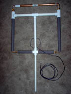
As before, assemble the main loop for verification, only now, also
attach the stator and rotor contact assemblies. These two capacitor
parts do not touch at the top of the loop, but it should be possible
to align their centers. Don't worry if the whole thing is very loose
right now. The union joints are very flexible and forgiving. So long
as it seems that the loop is square shaped and the capacitor pieces
are co-axial in the middle, you're in great shape.
Soldering
It is now time to solder together the five copper assemblies: the
bottom conductor, the left and right side conductors, the stator
assembly and the rotor contact assembly. I'll just list a few
soldering tips.
- Undo the unions and solder each piece separately.
- It is important to solder each joint completely, to minimize
electrical resistance. Due to the extremely low radiation resistance
of this loop, even a few milliohms have an impact on antenna
performance.
- There is no "trick" to the right and left side
conductors. Simply solder the copper parts together. About the only
advice I'll give here is that you should avoid getting solder in the
threads.
- The bottom conductor looks so simple, and it is, but there is one
catch. The threaded union ends don't fit through the 3/4" PVC
cross. My solution was to solder anyway, and use a dremel tool to
remove material from the cross until it fit. Another solution would
be to solder one end, allow it to cool, then install the PVC cross,
taking care to keep it far away and as cool as possible while
soldering on the other end.
- Avoid getting solder on the outer surfaces of the stator and the
rotor contact, since the dielectric sleeve and rotor fit snugly and
must slide freely. If you accidentally get a tiny bit of solder
farther from the joint than you had intended, you can always file it
off, but it's best to keep these surfaces pristine if possible.
Once the parts have cooled, try screwing them together again and see
if everything still fits as before. If not, make any necessary
adjustments.
Adding the insulation
Install pipe insulation material over the two side conductors, leaving
room to access the unions. Slide the PVC reducing tees over the
insulation to complete assembly of the side conductors.
For the bottom conductor, use two pieces of insulation material,
shoved into the PVC cross as far as possible and cut to size. I found
it helpful to use an aggressive twisting motion to force the
insulation material into the PVC cross.
 Final Assembly of the Capacitor
Slide the dielectric sleeve over the stator, all the way to the joint.
The sleeve is an inch longer than the stator, to prevent any
possibility of shorts or arcing.
Now slide the rotor partway over the sleeve. Some resistance is
normal, but if you find you are using excessive force, use the
procedure mentioned earlier to turn down the sleeve until a
comfortable fit is achieved.
Complete the capacitor assembly by inserting the rotor contact
assembly into the rotor. The union centers should be exactly 21"
apart. If they aren't, slide the dielectric sleeve onto or off of the
stator to adjust the overall length of the capacitor.
 The Complete Loop At Last
We're still missing a coupling loop and a 3/4" PVC handle, but
other than that, it is now possible to assemble the entire loop,
capacitor and all. It should look like the picture, other than the
missing coupling loop and handle.
 Adding the Coupling Loop
The coupling loop is a 15 inch (in circumference) loop. A simple
heavy wire or thin pipe, bent into a circle, open at the bottom and
connected to the 50 ohm coax, can do the trick. 1/4" copper line
worked quite well when I tried it.
For my antenna, I chose to use a faraday shielded loop, to reduce the
antenna's response to E-field interference (certain types of power
line noise, for example). I also decided that the flexible coax loop
was less likely to be damaged when transporting the antenna.
Here is a web
site that shows how to make a faraday shielded loop from coaxial
cable. It also has some good notes on magnetic loop antennas.
Testing the Antenna
Caution: Even at fairly low power levels, the RF voltages at
the top of the capacitor become quite high. For example, a 20W power
level will develop almost 2,000V across the capacitor. Also, check
this RF Safety web
site to make sure your exposure to RF is within acceptable
limits.
Connect your radio and tune to a frequency near 14 MHz. Somewhere
near 2/3 to 3/4 of full capacitance, the antenna should exhibit a
sharp response peak. You might find it useful at first to leave the
antenna alone and explore its tuning with an analyzer or your
transceiver, moving the capacitor and testing it again. You will have
to move your hands away from the antenna for each trial.
If everything is working properly, it should be possible (though
sometimes difficult until you are practiced and you have the
dielectric sleeve perfectly shaped) to achieve 1.0:1 SWR on any
frequency from 14 to 30 MHz.
Tip: use a marker to write on the capacitor so you can find favorite
frequencies again.
Links to Other Resources
- Small Transmitting
Loop Antennas This page by steve AA5TB is a wonderful resource, as
well as an excellent jumping-off point for further research. (His
list of links is far longer than mine -- check them out!)
- HF Pedestrian
Operation by PY1AHD This Brazilian Amateur's photos inspired me to
try to make a loop that I could use while walking around. These
photos really capture the excitement and fun of pedestrian operation
on HF.
- Elecraft
notes on magnetic loop antennas This is a very well done article
with lots of pictures, good explanations, and great ideas for further
experimenting.
- Magnetic
Loop Antennas This page documents some truly beautiful and
inspiring construction and offers sage advice borne of experience. It
also shows how to make a faraday coupling loop from coaxial cable.
- RF Safety
Calculator This site helps you determine whether your station is
within recommended safety guidelines.
- HFPack, The HF Portable
Group This is a web site and message base maintained by a group of
people who are interested in portable HF operation.
I got my first ham ticket in 1978 at the age of 12, and I've been
building the occasional antenna ever since. Most of them haven't
worked, but every once in a while, something interesting happens.
Recently I saw some pictures of magnetic loop antennas which permit
ambulatory operation on HF and I just had to try it!
Go
 to
-DeeT's Antenna Page.
David B. Thomas
(dt@dt.prohosting.com)
 Portable HF Transmitting Loop Antenna
 Portable HF Transmitting Loop Antenna
 Construction
 Building the Main Loop
 Building the Variable Capacitor
 Final Verification Before Soldering
 Final Assembly of the Capacitor
 The Complete Loop At Last
 Adding the Coupling Loop
 to
-DeeT's Antenna Page.